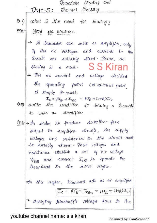

Minimum proper collector emitter voltage at any instant.Minimum proper base emitter voltage at any instant.To achieve faithful amplification the following basic condition most be satisfy : The theory of a transistor suggests that it will function properly if its input circuit (that is base-emitter junction) is forward biased and the output circuit (that is collector-base junction) is reverse biased at all times. The basic purpose of biasing is to keep the base emitter junction forward biased and collector base junction is reverse biased, during the application of signal.ĭuring amplification the magnitude of signal should increase and there should be no change in signal shape, this increase in magnitude of the signal without any change in shape is known as faithful amplification. The hybrid equivalent of a transis tor alone when connected in CC configuration is shown in Fig.Transistor biasing is required for proper operation of transistors in any circuit. Input signal source across its input terminals and load resistance across output terminals may be connected

Its V/I characteristics are described by the following equations The hybrid equivalent of the transistor alone when connected in CE configuration is shown in Fig.

It is all the reason to call it a hybrid equivalent circuit (b) Hybrid CE Circuit Incidentally, it may be noted that the ac equivalent circuit contains a Thevenin's circuit in the input and a Norton’s circuit in the output. It may be noted that no external dc biasing resistor or ac voltage sources have been connected to the equivalent circuit as yet. Similarly, ac voltage polarities have been taken by considering upper terminal positive and lower one as negative As per current convention, collector ie is shown flowing inwards though actually this current flows outwards as shown by the arrow inside the ac current source Similarly, current ic in the output terminals must equal the sum of two branch currents

#Transistor biasing and stabilization of operating point pdf generator
These equations are self-evident because applied voltage across input terminals must equal the drop over hib and the generator voltage Base Bias with Collector And Emitter Feedbacks It is a combination of (2) and (3) above. Base Bias with Collector Feedback It is also known as collector-to-base bias or collector feedback bias. Base Bias with Emitter Feedback This circuit achieves good stability of dc operating point against changes in β with the help of emitter resistor which causes degeneration to take place.ģ. Base Bias or Fixed Current Bias It is not a very satisfactory method because bias voltages and currents do not remain constant during transistor operation.Ģ. Some of the methods used for providing bias for a transistor are :ġ. collector-base junction is always reverse-biased This type of biasing is known as FR biasing emitter-base junction is always forward biased Biasing- Types of biasing- DC equivalent circuit of BJT- Load Line-DC and AC Load Line Analysis – Hybrid Model of BJT- Hybrid Model Analysis of CE, CB, CC - Calculation of Input Impedance, Output Impedance, Voltage Gain, Current Gain using hybrid model- Approximate Model of BJT- CE, CB and CC Analysis- Small signal equivalent circuit of BJT- Small Signal Analysis of CE, CB and CC.īiasing For proper working of a transistor, it is essential to apply external voltages of correct polarity across its emitter-base and collector-base junctions. UNIT – II TRANSISTOR BIASING CIRCUITS ANS SMALL SIGNAL ANALYSIS OF BJT AMPLIFIERS 9 Hrs.


 0 kommentar(er)
